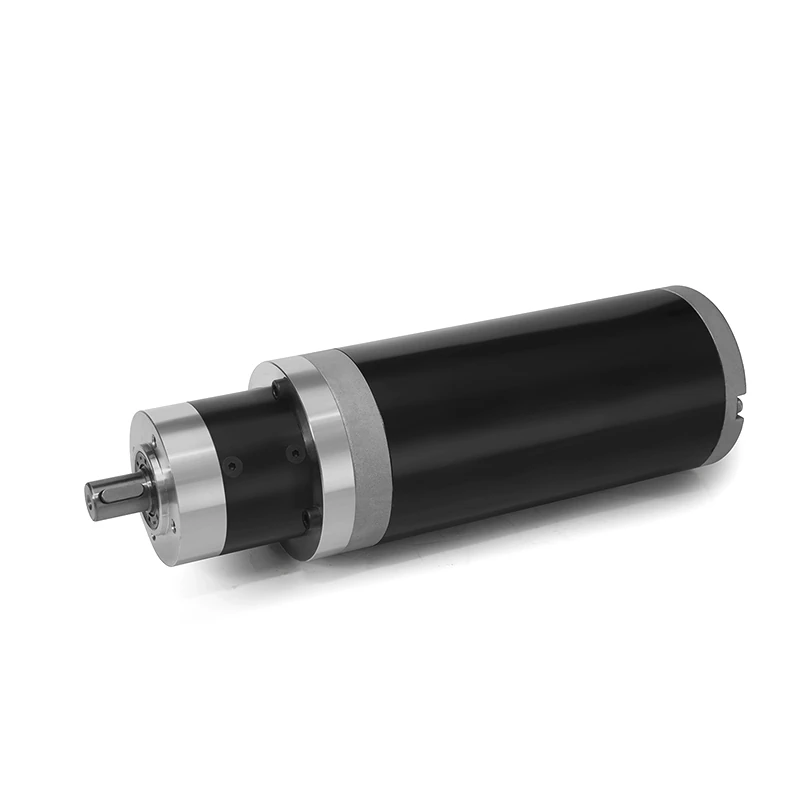
Essential Elements of a Brushless Geared Motor Setup and Their Interplay
Brushless Geared Motor Systems: A Detailed Look at Their Integral Components and Coordinated Operations
A brushless geared motor system is an efficient mechanism for transforming electrical power into mechanical energy, achieved through the seamless interplay of several key components. Below is an overview of these components and their respective roles:
Brushless DC Motor (BLDC): At the heart of the system lies the brushless DC motor, which is composed of a stationary stator with wound coils and a rotating rotor that contains permanent magnets. The stator’s coils are energized in a specific sequence, producing a magnetic field that rotates and interacts with the rotor’s magnets to generate motion.
Reducer or Gearbox: The reducer is an essential mechanical component that decreases the motor’s rotational speed while simultaneously boosting its torque output. It is equipped with a set of gears, such as spur, planetary, or helical gears, designed to achieve the necessary speed reduction and torque increase. This allows the motor’s speed to be adapted to the specific demands of the application and offers a mechanical advantage.
Encoders and Hall Effect Sensors: For precise control over the motor’s velocity, positioning, and direction, feedback mechanisms like encoders or Hall effect sensors are employed. Encoders offer exact position data by producing a series of pulses corresponding to the motor’s rotation, while Hall effect sensors identify the rotor’s position changes through magnetic field variations. This feedback is vital for the motor’s closed-loop speed and position control.
Motor Controller or Drive: The motor controller, also referred to as the drive or electronic speed controller (ESC), manages the power delivered to the motor, relying on input commands and sensor feedback. It dictates the sequencing and strength of the electrical current supplied to the motor coils, ensuring efficient operation, accurate speed regulation, and safeguarding against potential faults like overcurrent or excessive heat.
Power Supply Unit: The power supply unit is tasked with delivering the required electrical energy to the motor controller and the entire motor system. It transforms AC or DC power from the mains or batteries into the suitable voltage and current specifications for the motor and controller.
Communication Interface: Advanced brushless geared motors often include communication interfaces such as UART, SPI, or CAN, facilitating external control, monitoring, and communication with other system components or devices, thus enhancing the system’s integration capabilities and overall functionality.
Harmonized Operation: The system’s operation begins with the motor controller receiving command signals from a control unit or microcontroller, indicating the desired operational parameters such as speed and direction. Using these commands and feedback from the sensors, the controller calculates the optimal timing and magnitude of current to be delivered to the motor coils. The controller then activates the stator coils in a pattern that corresponds to the rotor’s current position, creating a dynamic magnetic field that drives the rotor’s rotation. The integrated reducer adjusts the motor’s rotational speed downward while increasing the torque output to suit the application’s load requirements. Through the concerted efforts of the motor, reducer, sensor feedback, and controller, the system achieves accurate and efficient mechanical motion, enabling the brushless geared motor system to be used in a variety of applications, including conveyor systems, robotic mechanisms, and automated equipment.
